

Surgical-microscope integrated ophthalmic imaging
Designing and fabricating a functional prototype integration of ophthalmic imaging technology for use in live surgery
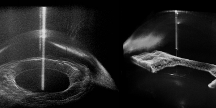
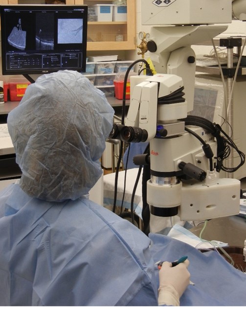
Ophthalmic surgery is largely performed using microscopes that leave much to be desired in the realm of stereoscopy (seeing with both eyes, which gives 3D depth perception). The standard top-down 2D view often leaves surgeons to rely on non-visual cues to perform micro-scale tasks. Optical coherence tomogrophy (OCT) allows for the visualization of the miniscule structures being operated on in 3D. Current OCT systems can take single images in 3D or real time images in 2D, but can not take real time images in 3D. An OCT imaging modality that is able to take micron-scale real time images in 3D would be useful for ophthalmic surgery feedback and guidance.
The Biophotonics Group at Duke University had been developing an OCT system for just this - real-time 3D image-guided ophthalmic surgery. The previous prototype of the system, while effective, was large and was a hindrance to normal movement around the patient by surgeons and assistants. I was responsible for taking a new compressed optical layout and mechanically integrating it into the currently used surgical microscopes.
One of the great challenges in this project was navigating the intersecting spheres of demands of the surgeons, the restrictions of the optical layout, and the lack of accurate CAD representation of the microscope. Guided questioning and discussion helped me decipher the complex maneuvers of the surgeon and her assistants so I could distill them into actionable design goals. In short, the need was for the new device to be as out of the way as possible since it had to be placed in such a high traffic area, i.e. a space where tools and instruments are passed or in the patient's body habitus.
The manufacturer of the surgical microscopes we were integrating the scanhead with was not eager to distribute engineering drawings of their designs, let alone CAD files. To work around this, I imagined splitting the miscroscope up into layers in the Z dimension as I do in my mind when I am working in CAD. To represent each layer physically, I cut and taped posterboard until I had "negatives" of each layer of the microscope. From these, and information on layer spacing, I could rebuild the scope in SolidWorks and more confidently build around it, bringing the optics up and out of the way with less guess work. These cardboard mockups also helped drive iterations on design informed by sessions with ophthalmic surgeons.
More details of the device and results can be found here:
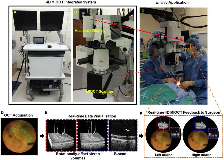
An older “chimey”style MIOCT scanner is pictured in ‘B’. The system I developed replaced that scanner.